Chapter 4Parameterized programs
Neural networks can be thought of as parameterized programs: programs with learnable parameters. In this chapter, we begin by reviewing how to represent programs mathematically. We then review several key neural network architectures and components.
4.1 Representing computer programs
4.1.1 Computation chains
To begin with, we consider simple programs that apply a sequence of functions to an input . We call such programs computation chains. For example, an image may go through a sequence of transformations such as cropping, rotation, normalization, and so on. In neural networks, the transformations are typically parameterized, and the parameters are learned, leading to feedforward networks, presented in Section 4.2. Another example of a sequence of functions is a for loop, presented in Section 5.8.
Formally, a computation chain can be written as Here, is the input, is an intermediate state of the program, and is the final output. Of course, the domain (input space) of must be compatible with the image (output space) of . That is, we should have . We can write a computation chain equivalently as A computation chain can be represented by a directed graph, shown in Fig. 4.1. The edges in the chain define a total order. The order is total, since two nodes are necessarily linked to each other by a path.

Figure 4.1: A computation chain is a sequence of function compositions. In the graph above, each intermediate node represents a single function. The first node represents the input, the last node the output. Edges represent the dependencies of the functions with respect to previous outputs or to the initial input.
4.1.2 Directed acyclic graphs
In generic programs, intermediate functions may depend, not only on the previous function output, but on the outputs of several different functions. Such dependencies are best expressed using graphs.
A directed graph is defined by a set of vertices or nodes and a set of edges defining directed dependencies between vertices. An edge is an ordered pair of vertices and . It is also denoted , to indicate that depends on . For representing inputs and outputs, it will be convenient to use incoming half-edges and outgoing half-edges .
In a graph , the parents of a vertex are the set of nodes pointing to , denoted . The children of a vertex are the set of nodes is pointing to, that is, . Vertices without parents are called roots and vertices without children are called leaves.
A path from to is defined by a sequence of vertices , potentially empty, such that . An acyclic graph is a graph such that there exists no vertex with a path from to . A directed acyclic graph (DAG) is a graph that is both directed and acyclic.
The edges of a DAG define a partial order of the vertices, denoted if there exists a path from to . The order is partial, since two vertices may not necessarily be linked to each other by a path. Nevertheless, we can define a total order called a topological order: any order such that if and only if there is no path from to .
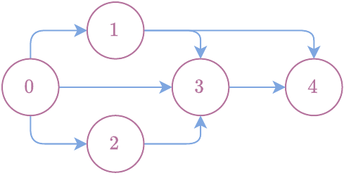
Figure 4.2: Example of a directed acyclic graph. Here the nodes are , the edges are . Parents of the node are . Children of node are . There is a unique root, , and a unique leaf, ; is a path from to . This is an acyclic graph since there is no cycle (i.e., a path from a node to itself). We can order nodes and as since there is no path from to . Similarly, we can order and as since there is no path from to . Two possible topological orders of the nodes are and .
4.1.3 Computer programs as DAGs
We assume that a program defines a mathematically valid function (a.k.a. pure function): the program should return identical values for identical arguments and should not have any side effects. We also assume that the program halts, i.e., that it terminates in a finite number of steps. As such a program is made of a finite number of intermediate functions and intermediate variables, the dependencies between functions and variables can be expressed using a directed acyclic graph (DAG). Without loss of generality, we make the following simplifying assumptions:
There is a single input .
There is a single output .
Each intermediate function in the program outputs a single variable .
We number the nodes as . Node is the root, corresponding to the input . Node is the leaf, corresponding to the final output . Because of the third assumption above, apart from , each variable is in bijection with a function . Therefore, node represents the input , and nodes represent both a function and an output variable .
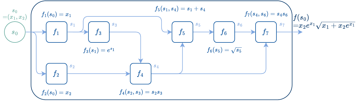
Figure 4.3: Representation of as a DAG, with functions and variables as nodes. Edges indicate function and variable dependencies. The function is decomposed as elementary functions in topological order.
Edges in the DAG represent dependencies. The parents of node , where , indicate the variables that the function needs to perform its computation. Put differently, the parents indicate the functions that need to be evaluated, prior to evaluating . An example of a computation graph in our formalism is presented in Fig. 4.3.
Executing a program
To execute a program, we need to ensure that we evaluate the intermediate functions in the correct order. Therefore, we assume that the nodes are in a topological order (if this is not the case, we need to perform a topological sort first). We can then execute a program by evaluating for Note that we can either view as a single-input function of , which is a tuple of elements, or as a multi-input function of . The two views are essentially equivalent.
The procedure for executing a program is summarized in Algorithm 4.1.
Algorithm 4.1: Executing a program
Functions: in topological order
Input: input
for do
Retrieve parent nodes
Compute
Output:
Dealing with multiple program inputs or outputs
When a program has multiple inputs, we can always group them into as with , since later functions can always filter out what elements of they need. Likewise, if an intermediate function has multiple outputs, we can always group them as a single output with , since later functions can filter out the elements of that they need.
Alternative representation: bipartite graphs
In our formalism, because a function always has a single output , a node can be seen as representing both the variable and the function . Alternatively, as shown in Fig. 4.4, we can represent variables and functions as separate nodes, that is, using a bipartite graph. This formalism is akin to factor graphs (Frey et al., 1997; Loeliger, 2004) used in probabilistic modeling, but with directed edges. One advantage of this formalism is that it allows functions to explicitly have multiple outputs. We focus on our formalism for simplicity.


Figure 4.4: Two possible representations of a program. Left: Functions and output variables are represented by the same nodes. Right: functions and variables are represented by a disjoint set of nodes.
4.1.4 Arithmetic circuits
Arithmetic circuits are one of the simplest examples of computation graph, originating from computational complexity theory. Formally, an arithmetic circuit over a field , such as the reals , is a directed acyclic graph (DAG) whose root nodes are elements of and whose functions are either or . The latter are often called gates. Contrary to the general computation graph case, because each is either or , it is important to allow the graph to have several root nodes. Root nodes can be either variables or constants, and should belong to .
Arithmetic circuits can be used to compute polynomials. There are potentially multiple arithmetic circuits for representing a given polynomial. One important question is then to find the most efficient arithmetic circuit for computing a given polynomial. To compare arithmetic circuits representing the same polynomial, an intuitive notion of complexity is the circuit size, as defined below.
Definition 4.1 (Circuit and polynomial sizes)
The size of a circuit is the number of edges in the directed acyclic graph representing . The size of a polynomial is the smallest among all representing .
For more information on arithmetic circuits, we refer the reader to the monograph of Chen et al. (2011).
4.2 Feedforward networks
A feedforward network can be seen as a computation chain with parameterized functions , for a given input and learnable parameters . Each function is called a layer and each can be seen as an intermediate representation of the input . The dimensionality of is known as the width (or number of hidden units) of layer . A feedforward network defines a function from to , where .
Given such a parameterized program, we can learn the parameters by adjusting to fit some data. For instance, given a dataset of pairs, we may minimize the squared loss on average over the data, w.r.t. . The minimization of such a loss requires accessing its gradients with respect to .
4.3 Multilayer perceptrons
4.3.1 Combining affine layers and activations
In the previous section, we did not specify how to parametrize the feedforward network. A typical parametrization, called the multilayer perceptron (MLP), uses fully-connected (also called dense) layers of the form where we defined the tuple and where we assumed that and are a matrix and a vector of appropriate size. We can further decompose the layer into two functions. The function is called an affine layer. The function is a parameter-free nonlinearity, often called an activation function (see Section 4.4). The value is often called the pre-activation value and the value is the activation value.
More generally, we may replace the matrix-vector product by any parametrized linear function of . For example, convolutional layers use the convolution of an input with some filters , seen as a linear map.
Remark 4.1 (Dealing with multiple inputs)
Sometimes, it is necessary to deal with networks of multiple inputs. For example, suppose we want to design a function , where and . A simple way to do so is to use the concatenation as input to a network . Alternatively, instead of concatenating and at the input layer, they can be concatenated after having been through one or more hidden layers.
4.3.2 Link with generalized linear models
When the depth is (only one layer), the output of an MLP is This is called a generalized linear model (GLM); see Section 3.4. Therefore, MLPs include GLMs as a special case. In particular, when is the softargmax (see Section 4.4), we obtain (multiclass) logistic regression. For general depth , the output of an MLP is This can be seen as a GLM on top of learned representation of the input . This is the main appeal of MLPs: they learn the feature representation and the output model at the same time! We will see that MLPs can also be used as subcomponents in other architectures.
4.4 Activation functions
As we saw in Section 4.3, feedforward networks typically use an activation function at each layer. In this section, we present various nonlinearities from scalar to scalar or from vector to scalar. We also present probability mappings that can be used as such activations.
4.4.1 ReLU and softplus
Many activations are scalar-to-scalar functions, but they can also be applied to vectors in an element-wise fashion. The ReLU (rectified linear unit) is a popular nonlinearity defined as the non-negative part of its input It is a piecewise linear function and includes a kink at . A multilayer perceptron with ReLU activations is called a rectifier neural network. The layers take the form where the ReLU is applied element-wise. The ReLU can be replaced with a smooth approximation (i.e., without kinks), called the softplus Unlike the ReLU, it is always strictly positive. Other smoothed variants of the ReLU are possible, see Section 13.4.
4.4.2 Max pooling and log-sum-exp
Many activations are vector-to-scalar functions: they reduce vectors to a scalar value. This scalar value can be seen as a statistic, “summarizing” the vector.
Max pooling
An example of vector-to-scalar reduction is the maximum value, also known as max pooling. Given a vector , it is defined as
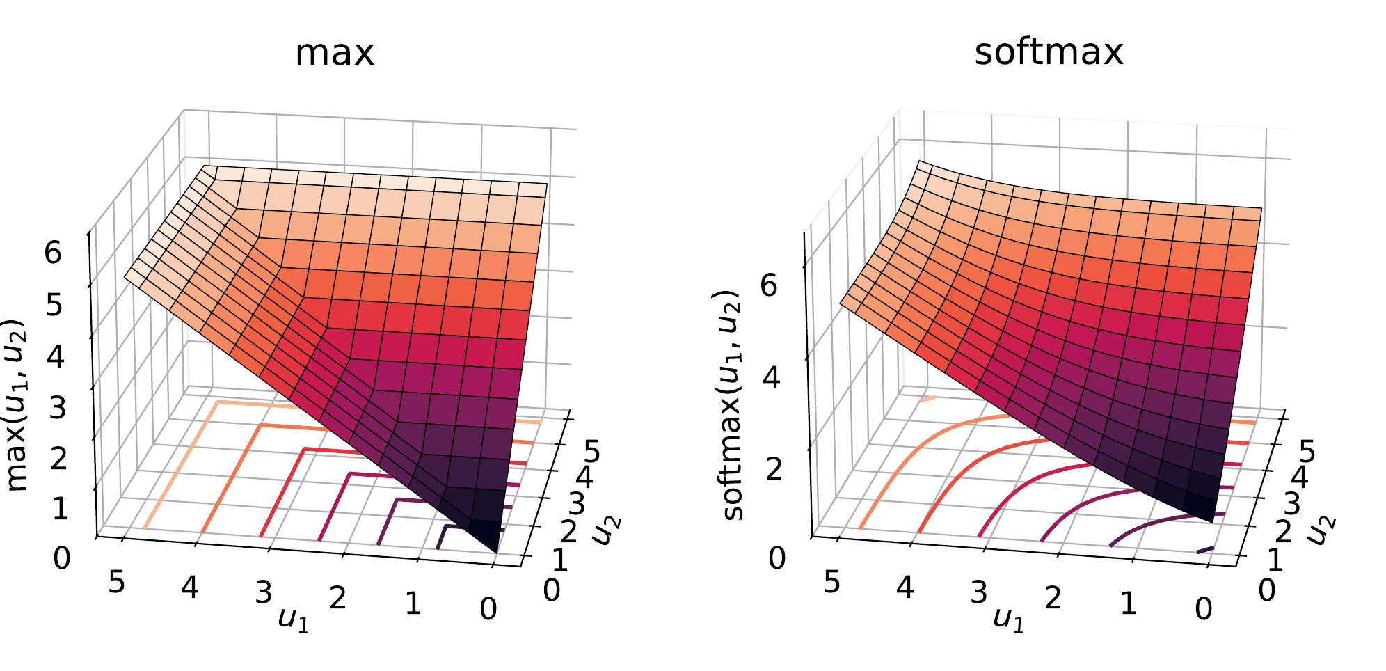
Figure 4.5: The maximum operator is a piecewise linear function. The log-sum-exp (a.k.a. softmax) is a smoothed approximation.
Log-sum-exp as a soft maximum
Another example of vector-to-scalar reduction is the log-sum-exp, As illustrated in Fig. 4.5, it is known to behave like a soft maximum. The log-sum-exp can be seen as a generalization of the softplus, as we have for all A numerically stable implementation of the log-sum-exp is given by where .
More generally, we can introduce a temperature parameter It can be shown that for all , Therefore, as . Other definitions of soft maximum are possible; see Section 13.5.
Log-sum-exp as a log-domain sum
Besides its use as a soft maximum, the log-sum-exp often arises for computing sums in the log domain. Indeed, suppose we want to compute , where . If we define and , we then have Written differently, we have the identity We can therefore see the log-sum-exp as the sum counterpart of the identity for products As an example, we use the log-sum-exp to perform the forward-backward algorithm in the log-domain in Section 10.7.1.
4.4.3 Sigmoids: binary step and logistic functions
Oftentimes, we want to map a real value to a number in , that can represent the probability of an event. For that purpose, we generally use sigmoids. A sigmoid is a function with a characteristic “S”-shaped curve. These functions are scalar-to-scalar probability mappings: they are used to squash real values to .
Binary step function
An example is the binary step function, also known as Heaviside step function, It is a mapping from to . Unfortunately, it has a discontinuity: a jump in its graph at . Moreover, because the function is constant at all other points, it has zero derivative at these points, which makes it difficult to use as part of a neural network trained with backpropagation.
Logistic function
A better sigmoid is the logistic function, which is a mapping from to and is defined as It maps to , to and it satisfies . It can therefore be seen as mapping from real values to probability values. The logistic can be seen as a differentiable approximation to the discontinuous binary step function . The logistic function can be shown to be the derivative of softplus, i.e., for all Two important properties of the logistic function are that for all and Other sigmoids are possible; see Section 13.6.
4.4.4 Probability mappings: argmax and softargmax
It is often useful to transform a real vector into a vector of probabilities. This is a mapping from to the probability simplex, defined by Two examples of such vector-to-vector probability mappings are the argmax and the softargmax.
Argmax
The argmax operator is defined by where denotes the one-hot encoding of an integer , that is, This mapping puts all the probability mass onto a single coordinate (in case of ties, we pick a single coordinate arbitrarily). Unfortunately, this mapping is a discontinuous function.
Softargmax
As a differentiable everywhere relaxation, we can use the softargmax defined by This operator is commonly known in the literature as softmax but this is a misnomer: this operator really defines a differentiable relaxation of the argmax. The output of the softargmax belongs to the relative interior of the probability simplex , meaning that it can never reach the borders of the simplex. If we denote , this means that , that is, can never be exactly or . The is the gradient of log-sum-exp, The can be seen as a generalization of the logistic function, as we have for all
Remark 4.2 (Degrees of freedom and invertibility of softargmax)
The softargmax operator satisfies the property for all and This means that the softargmax operator has degrees of freedom and is a non-invertible function. However, due to the above property, without loss of generality, we can impose (if this is not the case, we simply do , where ). Using this constraint together with we then obtain so that
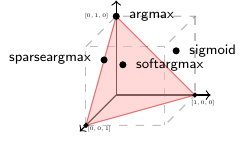
Figure 4.6: The argmax, the softargmax and the sparseargmax (see Section 13.7) are mappings from to the probability simplex . More precisely, the argmax maps to vertices of the probability simplex, the set of one-hot vectors , the softargmax maps to the relative interior and the sparseargmax maps to the entire probability simplex , including sparse probability vectors. Sigmoids applied element-wise return vectors in the hypercube , whose vertices are the vectors in .
4.5 Normalization layers
Intermediate states in neural networks, such as activations, can often attain a wide range of different values, potentially making it difficult for gradient descent to converge. To remedy this issue, we can introduce normalization layers at suitable locations in the network. In this section, we present the two most popular ones: batch normalization and layer normalization.
4.5.1 Batch normalization
Suppose we are given a batch of intermediate variables (such as activations or states) , where , obtained by applying some function to samples drawn from the training set (we omit the dependency on the layer index for clarity). In batch normalization (Ioffe and Szegedy, 2015), we normalize the values by calculating the standard score (a.k.a. z-score) across batch samples, Here, the means and the standard deviations are computed for each feature across samples in the batch. In practice, we often add a small value to to avoid division by zero or numerical instabilities. Moreover, we often rescale the values as where the means and standard deviations are learnable parameters.
One issue with batch normalization is that the means and standard deviations cannot be computed at inference time, as there is no notion of training batch (a single sample would lead to a variance of ). To address this issue, we can estimate means and standard deviations across the whole training set during the course of training, usually using a running average. A practical batch normalization implementation therefore needs to maintain mean and standard deviation statistics, so as to be able to use them at inference time.
4.5.2 Layer normalization
As an alternative, in layer normalization (Ba et al., 2016), we instead standardize the values by summing across features, This time, the means and the standard deviations are computed for each sample across features (as before, we often add a small value to ). Similarly to batch normalization, we often rescale the values as where the means and standard deviations are learnable parameters. A key advantage of layer normalization compared to batch normalization is that it is well defined at inference time, since it is applied on a per-sample basis and does not rely on the notion of a training batch. As a result, we can view layer normalization as a function that to any (regardless of whether it is part of a batch or not) associates
4.6 Residual neural networks
We now discuss another feedforward network parametrization: residual neural networks. Consider a feedforward network with layers , , , . Surely, as long as can exactly represent the identity function, the set of functions that this feedforward network can express should be a superset of the functions that , , can express. In other words, depth should in theory not hurt the expressive power of feedforward networks. Unfortunately, the assumption that each can exactly represent the identity function may not hold in practice. This means that deeper networks can sometimes be more difficult to train than shallower ones, making the accuracy saturate or degrade as a function of depth.
The key idea of residual neural networks (He et al., 2016) is to design layers , called residual blocks, that make it easier to represent the identity function. Formally, a residual block takes the form The function is called residual, since it models the difference . The addition with is often called a skip connection. As long as it is easy to adjust so that , can freely become the identity function. For instance, if we use where , it suffices to set and to a zero matrix and vector. Residual blocks are known to remedy the so-called vanishing gradient problem.
Many papers and software packages include an additional activation and instead define the residual block as where is typically chosen to be the ReLU activation. Whether to include this additional activation or not is essentially a modelling choice. In practice, residual blocks may also include additional operations such as batch norm and convolutional layers.
4.7 Recurrent neural networks
Recurrent neural networks (RNNs) are a class of neural networks that operate on sequences of vectors, either as input, output or both. Their actual parametrization depends on the setup but the core idea is to maintain a state vector that is updated from step to step by a recursive function that uses shared parameters across steps. Unrolling this recursion defines a valid computational graph, as we will see in Chapter 8. We distinguish between the following setups illustrated in Fig. 4.7:
Vector to sequence (one to many):
Sequence to vector (many to one):
Sequence to sequence (many to many, aligned):
Sequence to sequence (many to many, unaligned):
where stands for length. Note that we use the same number of parameters for each setup for notational convenience, but this of course does not need to be the case. Throughout this section, we use the notation for a sequence of vectors.
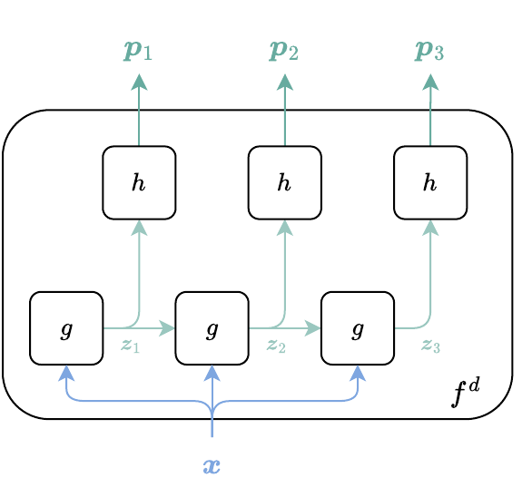
(a) One to many (decoder)
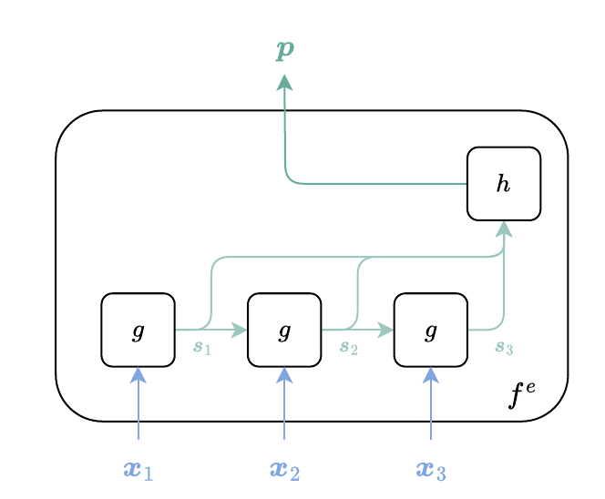
(b) Many to one (encoder)
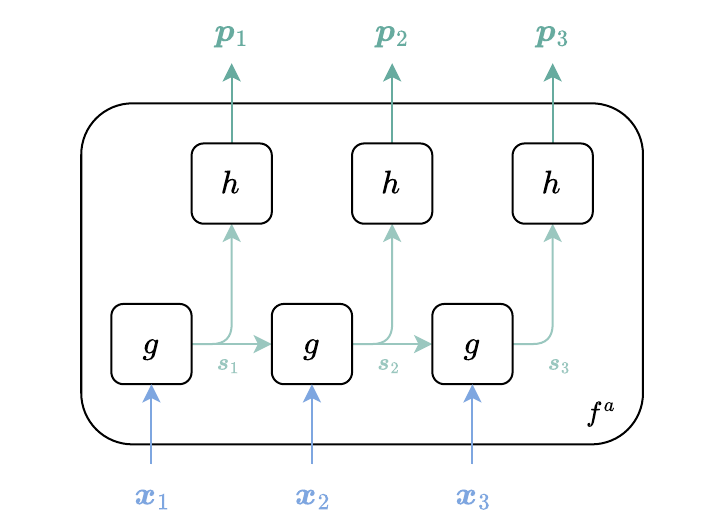
(c) Sequence to sequence aligned
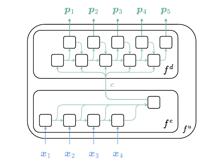
(d) Sequence to sequence unaligned
Figure 4.7: Recurrent neural network architectures
4.7.1 Vector to sequence
In this setting, we define a decoder function from an input vector and parameters to an output sequence . This is for instance useful for image caption generation, where a sentence (a sequence of word embeddings) is generated from an image (a vector of pixels). Formally, we may define through the recursion where . The goal of is to update the current decoder state given the input , and the previous decoder state . The goal of is to generate the output given the current decoder state . Importantly, the parameters of and are shared across steps. Typically, and are parametrized using one-hidden-layer MLPs. Note that has multiple inputs; we discuss how to deal with such cases in Section 4.3.
4.7.2 Sequence to vector
In this setting, we define an encoder function from an input sequence and parameters to an output vector . This is for instance useful for sequence classification, such as sentiment analysis. Formally, we may define using the recursion where . The goal of is similar to , except that it updates encoder states and does not take previous predictions as input. The pooling function is typically parameter-less. Its goal is to reduce a sequence to a vector. Examples include using the last state, the average of states and the coordinate-wise maximum of states.
4.7.3 Sequence to sequence (aligned)
In this setting, we define a function from an input sequence and parameters to an output sequence , which we assume to be of the same length. An example of application is part-of-speech tagging, where the goal is to assign each word to a part-of-speech (noun, verb, adjective, etc). Formally, we may define as where . The functions and are similar as before.
4.7.4 Sequence to sequence (unaligned)
In this setting, we define a function from an input sequence and parameters to an output sequence , which potentially has a different length. An example of application is machine translation, where the sentences in the source and target languages do not necessarily have the same length. Typically, is defined as the following two steps where , and where we reused the previously-defined encoder and decoder . Putting the two steps together, we obtain
This architecture is aptly named the encoder-decoder architecture. Note that we denoted the length of the target sequence as . However, in practice, the target length can be input dependent and is often not known ahead of time. To deal with this issue, the vocabulary (of size in our notation) is typically augmented with an “end of sequence” (EOS) token so that, at inference time, we know when to stop generating the output sequence. One disadvantage of this encoder-decoder architecture, however, is that all the information about the input sequence is contained in the context vector , which can therefore become a bottleneck.
4.8 Transformers
Transformers (Vaswani et al., 2017) are one of the most successful recent developments in deep learning. In this section, we review Transformers, component by component.
4.8.1 Attention
The goal of an attention layer is to map a sequence of inputs to a sequence of outputs , of same dimension. A natural idea is to define each output element using a linear combination of the input elements, We typically use a convex combination: we assume that the combination weights are such that . This ensures that increasing a coefficient is made at the expense of decreasing another coefficient , for . Let us form the matrices and by stacking and , seen as row vectors. Let us also form the attention matrix gathering the entries , where denotes the set of row-wise stochastic matrices. Then, we can rewrite attention succinctly as Following Section 6.2, we can view attention as a soft dictionary lookup. From this perspective, the matrix plays the role of dictionary values, and the attention matrix can be defined as where and play the roles of queries and dictionary keys, respectively. Intuitively, can be seen as a similarity matrix containing the similarities between queries and dictionary keys. Putting everything together, we can define attention as In masked attention, we additionally incorporate a mask , where denotes the Hadamard product (element-wise multiplication). The mask can be used to force some attention weights to be zero, by setting the corresponding mask entry to . For instance, in decoder-only architectures (Section 4.8.8), the mask will prove useful to define causal attention for autoregressive models.
Remark 4.3 (Scaled attention)
Practical implementations often use scaled attention, where a factor of is used within the soft-argmax, in order to reduce the variance (Vaswani et al., 2017, Footnote 4). We omit this detail for clarity.
4.8.2 Self-attention
Suppose we are given a sequence of feature vectors , that we gather as a matrix . To define the attention weights , a natural idea is to consider the similarity between and , as measured by the inner product . To ensure that , we can then define In matrix notation, this can be written where is applied in a row-wise fashion. The matrix is the Gram matrix associated with the row vectors . In the notation of the previous section, this corresponds to using with . In other words, the elements of the sequence “pay attention” to each other. This is called self-attention.
So far, the formulation we described is parameter-free. To give more expressive power to the self-attention layer, Vaswani et al. (2017) proposed instead to define , and by projecting as using the learned weight matrices Importantly, the size of the weight matrices is independent of the length of the sequences. This allows self-attention to work with sequences of arbitrary length.
4.8.3 Multi-head attention
In order to be able to capture multiple patterns of attention, Vaswani et al. (2017) found it beneficial to define attention heads where using the learned weight matrices Let us denote the concatenation of the attention heads by Vaswani et al. (2017) then define multi-head attention as where is a learned matrix. We summarize the procedure in Algorithm 4.2. We use a for loop for the sake of clarity; a GPU-friendly implementation would instead be based on a single matrix multiplication.
Algorithm 4.2: Multi-head attention with attention heads
Input: , optional mask
Parameters: , , ,
for do
Output:
4.8.4 Transformer layer
To improve training efficiency, we can introduce residual connections and a first layer normalization (Section 4.5.2), to define To improve expressiveness, a Transformer layer further uses an MLP and a second layer normalization, The subscripts in are used to emphasize that the two layers use their own parameters. In addition, normalization is applied in an element-wise (token-wise) fashion. The MLP block typically uses a single hidden layer with an activation function , such as a GELU (Gaussian error linear unit); see Algorithm 4.3. Because of the use of residual connections, the input and output dimensions of the MLP block must be the same.
Algorithm 4.3: Transformer’s MLP block
Input:
Parameters:
Output:
Remark 4.4 (Post-normalization vs. pre-normalization)
Our description of the Transformer layer follows the original formulation (Vaswani et al., 2017), which uses post-normalization. Some implementations instead rely on pre-normalization, that is,
4.8.5 Transformer block
A Transformer layer can be iterated times (each time with different parameters) to define a Transformer block of depth . Keeping the dependency on parameters implicit, we can see a Transformer, with an optional mask , as a function from to . The Transformer takes a sequence and uses the inter-dependencies between sequence elements to produce a representation of that sequence. We summarize the procedure in Algorithm 4.4. The , and blocks are indexed by to emphasize that their parameters are different for each iteration.
Number of parameters and computational complexity
The Transformer layer can be seen as a function from to . To offer the same function signature, a standard multi-layer perceptron would have needed parameters and a forward pass through the network would have had a time complexity of as well. In contrast, a Transformer layer has parameters. Self-attention has a complexity of and the final MLP layer has a complexity of .
Algorithm 4.4: Transformer block of depth
Input: , optional mask
Parameters: Multi-head attention parameters, MLP parameters and layer norm parameters (each depth uses different parameters)
for do
▷ Residual connection
▷ MLP layer
Output:
4.8.6 Token encoding
Text can be represented as a sequence of discrete symbols, often called tokens. Here, each token , where is the vocabulary size, can correspond to words, subwords, or even individual characters, depending on the tokenization procedure. To obtain a sequence of continuous vectors , where , it is common to use an embedding layer. This layer transforms into using the linear projection where is the one-hot encoding of and is a learnable embedding matrix. The column can be interpreted as the continuous representation of token . Usually, the vocabulary includes special tokens such as “BOS” (beginning of sequence), “EOS” (end of sequence) and “PAD” (padding token, to ensure that the sequence is of length ).
4.8.7 Positional encoding
Due to their parameterization, Transformers are equivariant with respect to permutations: permuting the input sequence and applying the Transformer is equivalent to applying the Transformer and permuting the output sequence. Formally, for any permutation matrix of size and input sequence seen as a matrix , we have This means that Transformers treat an ordered sequence as a multi-set (a modification of the concept of a set that allows for multiple instances of its elements). To leverage order information in a Transformer, several approaches are possible (Dufter et al., 2022): adding positional encoding (either absolute or relative), modifying the attention matrix and pre-processing the input sequence with an RNN. To add positional encoding, one typically adds a vector representing the position to the corresponding element , An ideal positional encoding should work with any sequence length.
Learned positional encoding
Similarly to the token encoding, a simple way to define a positional encoding is to use an embedding layer. Each position is transformed into a position vector by where is the one-hot encoding of and is a learnable embedding matrix. The column can be interpreted as the continuous representation of position .
Sinusoidal positional encoding
Instead of learning the positional encoding, we can define it in a heuristic manner. For instance, Vaswani et al. (2017) proposed the sinusoidal positional encoding , defined by where and where is a constant, set to by the authors. We can gather the values in a position encoding matrix , as depicted in Fig. 4.8.
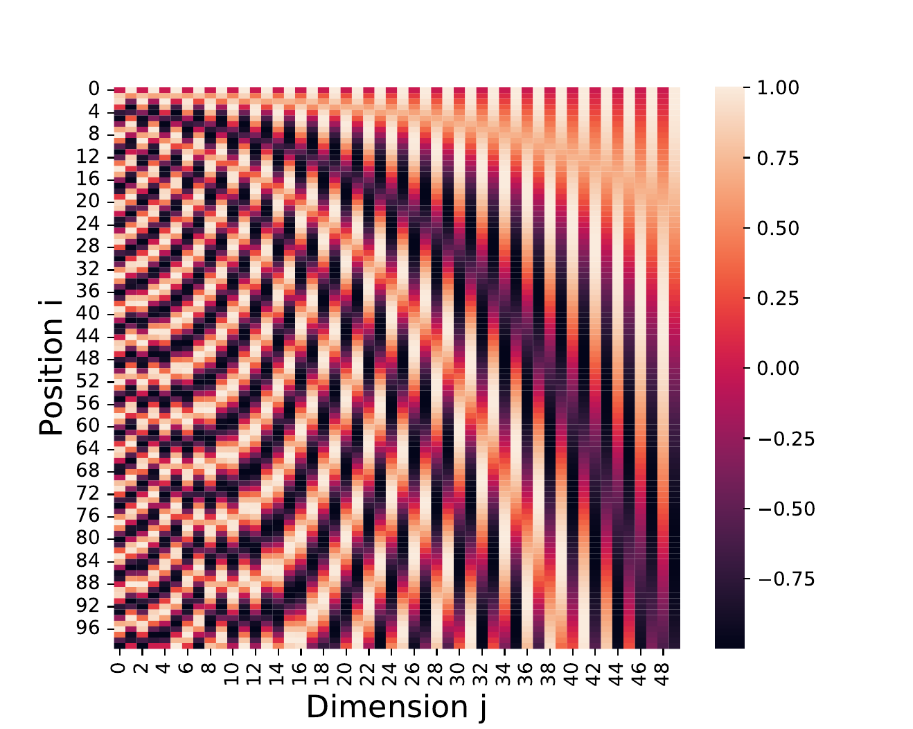
Figure 4.8: Heatmap of a positional encoding matrix , with , , and . The values belong to the range .
On first sight, sinusoidal positional encoding may seem a bit mysterious. To gain some intuition, it is useful to compare it to a discrete binary encoding of integers, We see that the bits alternate more frequently between and as we go from right to left. The sinusoidal positional encoding achieves a similar behavior, but is continuous. Indeed, each coordinate is associated with a sine wave (when is even) or a cosine wave (when is odd). The wavelength or period of the wave associated with is and its frequency is . Since is a decreasing function of , we see that the waves oscillate more frequently when is small. This behavior is illustrated in Fig. 4.9.
Stacking sine and cosine waves has been used for creating random Fourier features (Rahimi and Recht, 2007; Sutherland and Schneider, 2015). These use waves of random frequencies, while sinusoidal positional encoding uses waves of increasing frequency. These approaches therefore mainly differ in the way we choose wave frequencies.
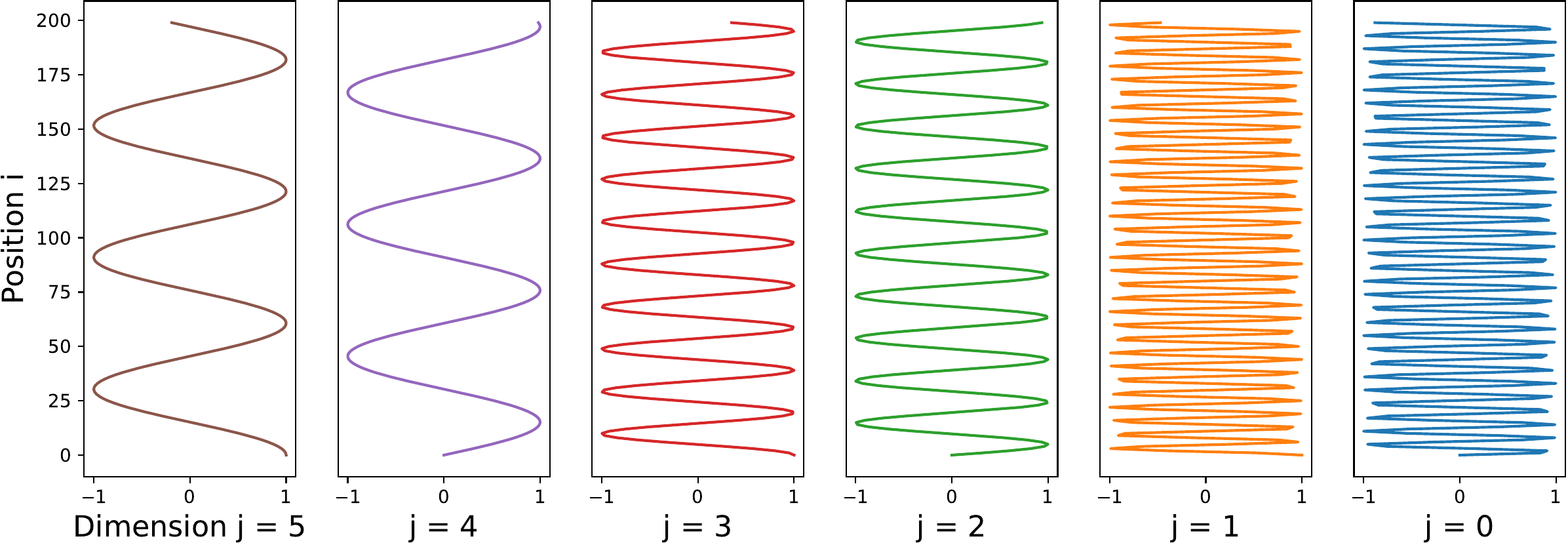
Figure 4.9: Using a sinusoidal positional encoding, each coordinate is associated with a sine or cosine wave. In analogy with a binary encoding, in which lower bits alternate between and more frequently than higher bits, the wave associated with oscillates more frequently when is small.
Recovering relative positional information
An important property of the sinusoidal positional encoding is that can be represented as a linear function of , for any offset (Vaswani et al., 2017; Zhang et al., 2021). The model should therefore be able to easily learn to attend by relative positions. Indeed, using the trigonometric identities for angle sums we have for even Therefore, can be linearly projected to , by applying a rotation matrix. This allows a Transformer to easily learn to attend by relative positions.
Rotary positional encoding (RoPE)
Another popular approach for taking into account absolute positional information in self-attention is RoPE (Su et al., 2024), which stands for rotary positional encoding. For simplicity, we briefly explain the idea with a single attention head and . Suppose we have a sequence already encoded with token encoding. We then define the query and key vectors as where is a rotation matrix. The main intuition is that we are rotating the -dimensional vector by an angle which is a multiple of the position . In contrast to the learned and sinusoidal positional encodings, the weight matrices and are applied before applying RoPE, not after.
When , is defined as the rotation matrix for some angle and position . Using Euler’s formula we note that for and is equivalent to for and . See Su et al. (2024) for a detailed derivation of RoPE’s formula.
When , assuming is even, is defined as where . In practice, we never materialize as a matrix, since it would be very sparse, but rather view it as a linear map applied to an arbitrary vector , Once we computed and , we can use as usual. For multi-head attention, we simply apply the same approach for each attention head.
As analyzed by Su et al. (2024), RoPE satisfies several valuable properties. In particular, it is flexible w.r.t. the sequence length and despite being an absolute encoding, it manages to also capture relative distance between tokens. It therefore has the merits of both absolute and relative positional encodings.
4.8.8 Decoder-only architectures
Defining a language model
Transformers were originally developed to create encoder-decoder architectures for machine translation (Vaswani et al., 2017). However, in the context of language modelling, Transformers are now routinely used for decoder-only autoregressive architectures. Suppose we are given a sequence of discrete symbols (if a sequence has less than elements, we can use padding symbols). The goal of (unconditional) language models is to create a function producing the joint probability, Using the chain rule of probability (Section 10.1), without loss of generality, we can write If the maximum length is very large, it is more practical to only consider a context window of size , This amounts to defining a higher-order Markov chain (Section 10.4.3). Using this approach, creating a language model then boils down to defining a function Let us assume that the sequence of discrete symbols has been mapped to a sequence of continuous vectors using token encoding (Section 4.8.6) and positional encoding (Section 4.8.7). Using a causal Transformer block, we can obtain a representation of the current context, To ensure that the Transformer only relies on past tokens to predict the current token, the mask matrix is set to a matrix of size , with the elements of the lower part set to , and the elements of the upper part set to . To reduce this to logits in , we usually use the last element of the context and apply a linear model, to obtain where is a learned “disembedding” matrix. To obtain a valid probability distribution, we apply a soft-argmax on the logits , Finally, we can now define
Remark 4.5 (Weight tying)
Instead of learning a separate disembedding matrix , a frequently used technique is to set , where is the embedding matrix from Section 4.8.6. This weight tying reduces the number of parameters to learn and is shown to work well in practice (Press and Wolf, 2016).
Training
Let us gather the Transformer parameters (multi-head attention, MLP, layer norm) as . The decoder-only Transformer with a context window of size then defines a parametric probability distribution Given a corpus of sequences , we usually seek the parameters by maximizing the log-likelihood, This amounts to using a logistic (cross-entropy) loss in a token-wise fashion. Importantly, the context used to predict the next token always comes from the data, not from the tokens generated by the model. This is called teacher forcing and makes Transformer training highly parallelizable. The objective is usually solved approximately using stochastic gradient algorithms. To maximize GPU utilization, sequences of variable lengths are usually packed together in order to form batches.
Sampling
A decoder-only Transformer with a context window of size can be seen as forming a higher-order Markov chain, which is a special case of Bayesian network. To generate a sequence from the model, we can therefore use ancestral sampling (Section 10.5.3), where denotes the beginning-of-sequence (BOS) token. The sampling stops when the end-of-sequence (EOS) token is generated or when a maximum length is reached. The generated sequences are i.i.d. .
Because sampling happens one token at a time, it is highly sequential. The Transformer block is called sequentially as To avoid repeating the same computations again and again, assuming that a causal mask is used, the past key and value matrices used in multi-head attention (Section 4.8.3) are usually stored in the so-called KV cache.
4.8.9 Encoder-only architectures
Encoder-only Transformers can be used for learning to represent sequences. The most prominent example is BERT (Devlin et al., 2019), which stands for bidirectional encoder representations from transformers. BERT uses Algorithm 4.4 without causal mask (hence “bidirectional” in the acronym). Discrete sequence elements are transformed to vectors using token encoding, positional encoding and potentially segment encoding. For reasons that will become clear below, the first token of every sequence is always a special classification token [CLS]. Training is broken down into two phases: pretraining and finetuning.
Pretraining
Since pre-training is performed on an unlabeled corpus, it is necessary to synthetically generate prediction tasks.
In masked prediction, a percentage (typically 15%) of the input tokens are randomly masked. The model is then trained to predict the original vocabulary ID of the masked tokens, given the context provided by the unmasked tokens. This forces the model to learn a rich, bidirectional representation of the language. The masking strategy involves:
80% of the time, replacing the chosen token with
[MASK],10% of the time, replacing the chosen token with a random token from the vocabulary,
10% of the time, keeping the chosen token unchanged.
In next sentence prediction, the model is trained to understand the relationship between two sentences. For each training example, BERT is given two sentences, and . 50% of the time, B is the actual next sentence that follows A in the original document (labeled IsNext). The other 50% of the time, is a random sentence from the corpus (labeled NotNext). A special [CLS] token is prepended to the input sequence, and its final hidden state is used to predict whether sentence follows sentence A. The [SEP] token separates the two sentences.
Finetuning
After pre-training on a massive corpus, the pretrained BERT model can be finetuned for various downstream NLP tasks (e.g., text classification, question answering, named entity recognition) by adding a small, task-specific output layer on top of the pre-trained Transformer encoder. The entire model, including the pretrained weights, is then finetuned on the labeled data for the specific task. For classification tasks, the final hidden state corresponding to the class token [CLS] is used. For tagging tasks (token-level classification) such as named entity recognition (NER) or part-of-speech (POS) tagging, the final hidden state of each token is used. For question answering tasks, which usually involve finding a span (start and end token) within a given text, this is treated as two token-level classification problems: one for the start token and one for the end token.
4.8.10 Encoder-decoder architectures
The encoder-decoder architecture was the original architecture proposed in the seminal Transformer paper (Vaswani et al., 2017). It can be used for sequence-to-sequence tasks, such as machine translation, summarization and question answering. We denote the input sequence by and the output sequence by .
Encoder
The role of the encoder is to produce a rich representation of the input sequence , which serves as a context for the subsequent decoding phase. As in encoder-only architectures, this is achieved by using Algorithm 4.4 without causal mask. The multi-head self-attention layer allows the encoder to weigh the importance of different tokens in the input sequence relative to each other. For each token in the input, it computes a representation that incorporates information from all other tokens in the same sequence. The encoder block uses its own parameters for each sub-component (multi-head attention, layer norm, MLP). In particular, multi-head attention uses parameters , , and .
Decoder
The role of the decoder is to generate the output sequence one token at a time, based on the encoded representation from the encoder and the previously generated tokens . The decoder differs in the way attention is applied. First, we apply causal multi-head self-attention to obtain a representation corresponding to the previously generated tokens . Second, we apply multi-head cross-attention. The key difference with multi-head self-attention is that the key, query and value matrices are defined as where , and are the weight matrices used for the decoder. Subsequently, MLP and layer norm layers are applied, similarly as before.
Differences with decoder-only architectures
An encoder-decoder architecture provides a dedicated component for understanding the input and another for generating the output. It allows for a bidirectional understanding of the input. It is therefore best suited for sequence-to-sequence (seq2seq) tasks where the input and output sequences may have different domains or modalities.
Decoder-only models, on the other hand, are streamlined for generating text by continuously predicting the next token, leveraging a single, powerful autoregressive mechanism. That being said, due to their simplicity, decoder-only architectures are now increasingly being used even for seq2seq tasks, by prepending the input (prompt) to the context. This means that the input is subject to the causal mask, but the performance remains remarkably strong.
4.9 Summary
Programs can be mathematically represented as a directed acyclic graph.
Neural networks are parameterized programs.
Feedforward networks are parameterized computation chains.
Multilayer perceptrons (MLPs), residual neural networks (ResNets) and convolutional neural networks (CNNs) are all particular parametrizations of feedforward networks.
Transformer blocks are designed to process sequences of variable-length, but they are equivariant to permutations and therefore require positional encoding, in order to leverage positional information.